The first electromagnetic transmission electron microscope was constructed by E. Ruska when improving the cathode ray oscilloscope in the high voltage laboratories of Berlin Technical University headed by M. Knoll. The coils of that first model were not yet iron-sheathed.
Early in 1931 a laboratory model was constructed which included two short coils arranged one after the other along the optical axis. Each coil was provided with a specimen stage. The specimens were apertures carrying fine wire grids in order to be able to study specimens of different shape.
On April 7, 1931, E. Ruska and M. Knoll succeeded in taking the first two-stage image of such grids at a magnification of seventeen times. The optical quality was similar to that of a good magnifying glass, and it was still unknown whether it would be possible to achieve a resolution better than that of the light microscope.
The accelerating voltage of the laboratory model was 75 kV. A gas discharge tube with cold cathode served as an electron source. The image could be observed from outside, and the fluorescent screen could be photographed through a window.
The first results encouraged E. Ruska to continue his work since the resolution of an electron microscope would at any rate not be limited by the wavelength of light.
In order to be able to demonstrate submicroscopic resolution in electron micrographs the magnification had to exceed the useful magnification of the light microscope. Sufficient magnifications at a reasonable microscope column size and a low number of imaging stages can only be achieved by using electron lenses of short focal length.
In 1932, B. von Borries and E. Ruska proposed to use conical pole-pieces in the annular gap of the iron sheath of the coil in order to concentrate the field into a smaller axial region. This was the first "pole-piece lens" which is now used in all types of magnetic transmission electron microscopes.
In 1933 E. Ruska studied the pole-piece experimentally and constructed an improved electron microscope capable of attaining magnifications of up to 12000 times. This highly magnifying electron microscope was called super microscope because this instrument produced the first micrograph with a resolution exceeding that attainable with the optical microscope. Structures in the 50 nm range were clearly resolved.
The new microscope was the first to have a condenser lens in order to produce the current density at the specimen required for high magnifications. The two magnifying lenses, objective and projector, consisted of iron-shrouded pole-piece lenses. The objective lens could be operated at a focal length as short as 6.5 mm. The highest accelerating voltage was 75 kV.
The microscope was equipped with a revolving specimen stage allowing to change specimens arranged in eight specimen holders without interrupting the vacuum. The image formed on a viewing screen was photographically recorded from outside.

This microscope was the first one to be used for technical applications. Its operation was simplified. A more convenient and rapid change of specimens and plates was achieved using airlocks.
The airlock system allowed to take the specimens closer to the field of the objective lens. The objective lens now worked at a focal length as short as 5.4 mm, which could later be reduced to 2.5 mm. The two-stage magnification was 30000 times, and the initial point resolution of 7 nm was later reduced to about 3 nm. A reduction of the length of the imaging system to 580 mm permitted a convenient observation of both the intermediate and the final image.

The microscope had now an airlock for rapid change of photographic plates allowing internal photography and, consequently a reduction of beam exposure to the specimen. Diffraction patterns could be taken to obtain further information on the structure of the specimen.
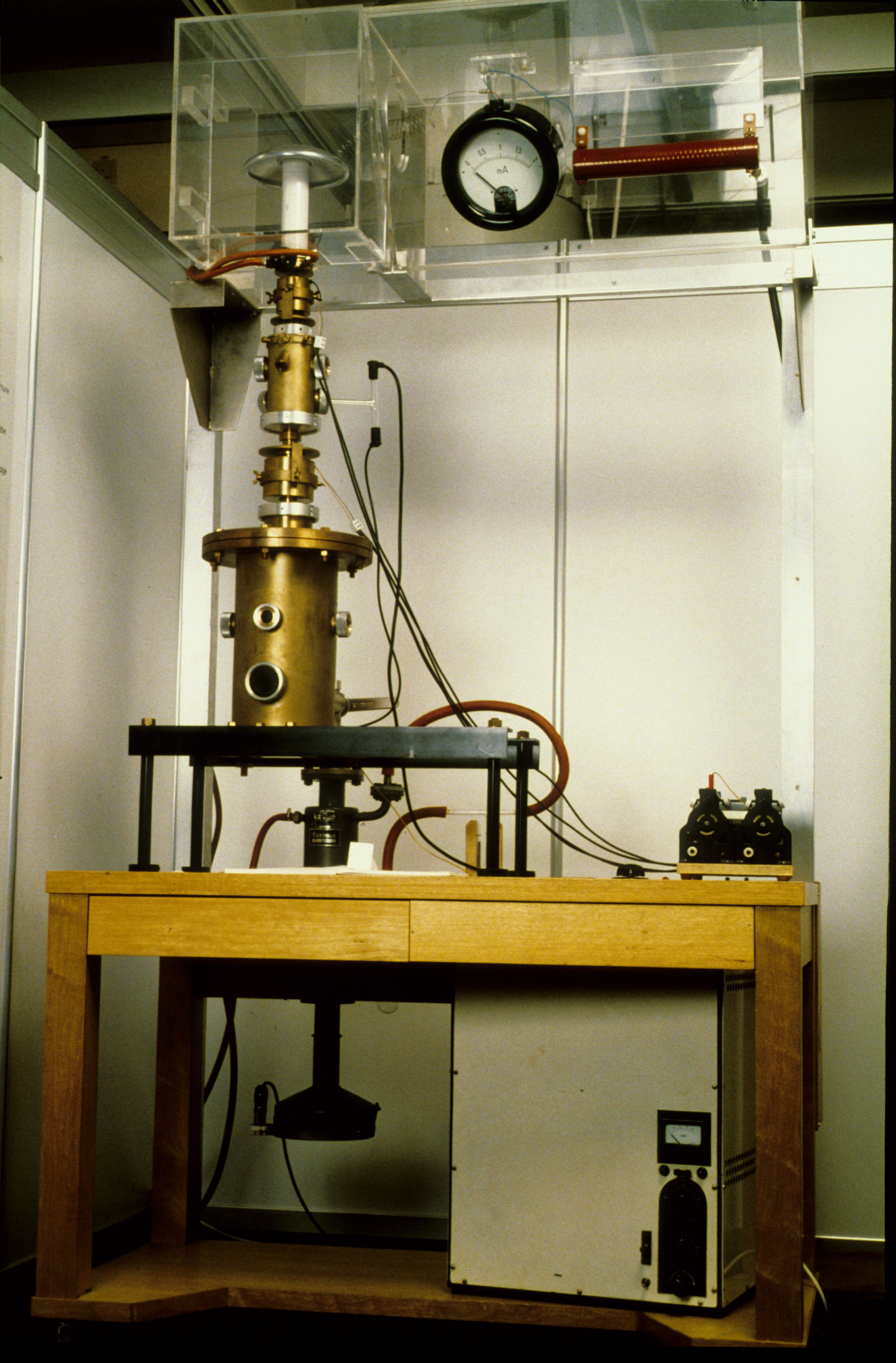
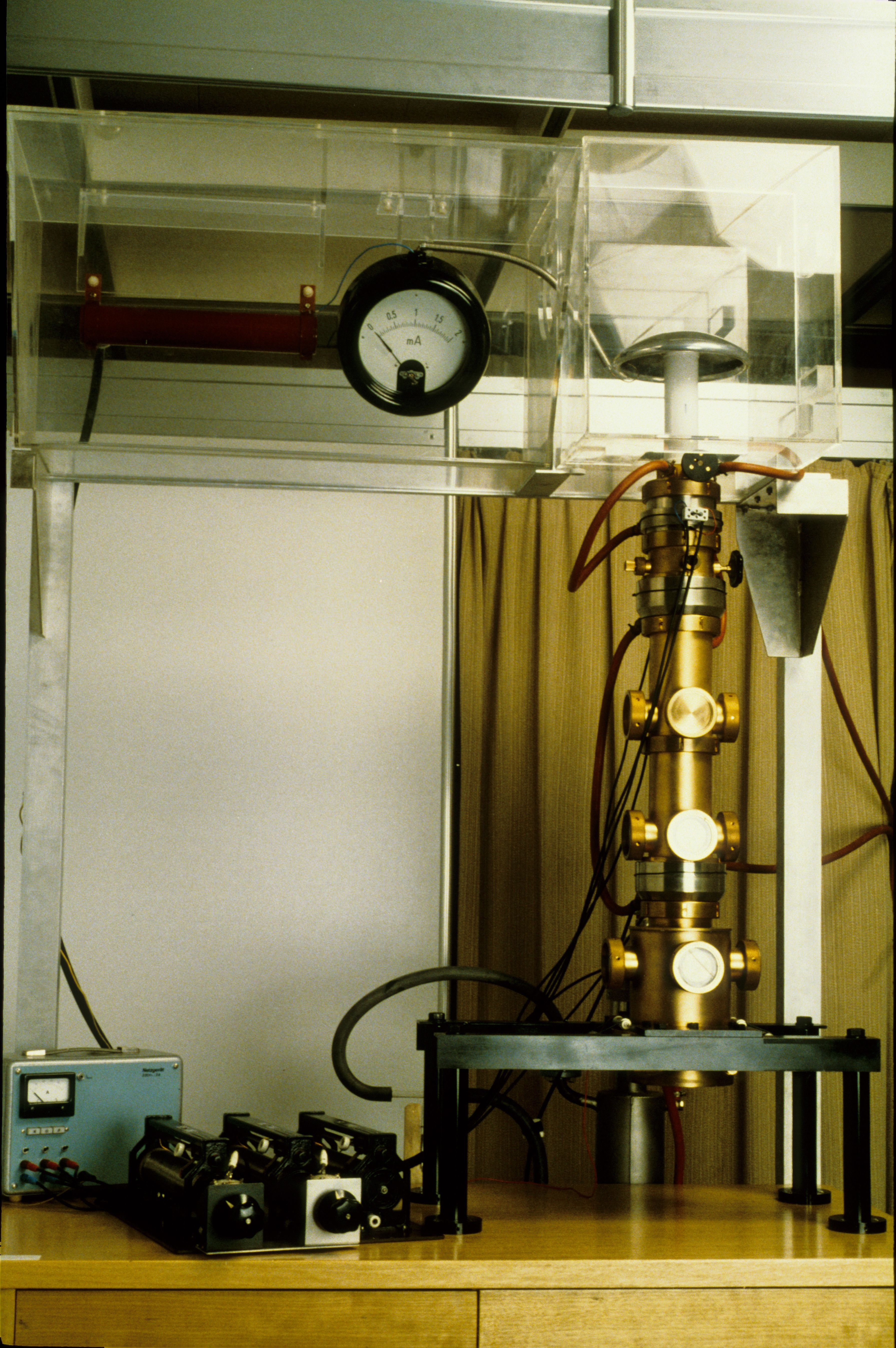
The vacuum pumps and some auxiliary electrical equipment were housed in a separate metallic case, parts at high voltage were protected against contact in an elevated trough. The microscope proper was placed on a solid table, and below was a switch panel holding the necessary operating controls. A swiveling mechanism permitted the column to be opened for dismantling or cleaning purposes.

Late in 1939 H. Mahl constructed the first electrostatic transmission electron microscope at the AEG research laboratories in Berlin. This instrument was a microscope of conventional design with two magnifying electrostatic high voltage single lenses of short focal length arranged behind the specimen. Symmetrical unipotential lenses were used for the objective and the projector to make the focal length independent of the accelerating voltage. For this reason it was sufficient to keep the variations of voltage below about 1 %.
The electrostatic transmission electron microscope had a much simpler design, but at higher voltages it was not as reliable as the electromagnetic electron microscope. Comparable magnifications required either a larger size of the column or a higher number of magnifying steps because some electrode distance is required to prevent electric arcing.
Since 1947, a more advanced instrument, the EM 7 with three imaging stages, was produced by the Süddeutsche Laboratorien Mosbach. The electrons emitted from a thermionic cathode and accelerated to 50 kV were directly focused onto the specimen without requiring a condenser lens. The objective lens formed a magnified real image in the intermediate image plane. A small central part of the intermediate image was further magnified by an electrostatic double projector containing two lenses operated separately or together. The electron optical magnification could be switched to 1500, 5000 or 15000 times, the resolution limit was 2 nm. When the EM 7 was constructed this value was the world record in resolution.
The microscope column was arranged on a table fixed to a stand containing the pumps and the battery necessary for heating the electron source, and carrying the operating knobs.

The instrument was already equipped with a stigmator for compensating astigmatism. A locking system made the specimen airlock foolproof. A storage device contained 24 plates which could be removed individually without interrupting the vacuum. Manipulation errors were excluded by extensive automatic control.

In experiments demonstrating the focusing effect of an electrostatic cylinder lens, H. Johannson invented at the end of 1931 the electrostatic emission microscope at the Berlin laboratories of AEG.
Using electrons emitted from an electron gun consisting of a thermionic cathode and an electrostatic accelerating lens Johannson succeeded in imaging the cathode surface at a magnification of 60 times. Immediately in front of the emitting cathode a circular aperture was placed and maintained at a positive potential of 10-30 V with respect to the cathode. A subsequent aperture had a positive potential of about 200-600 V equal to that of the fluorescent screen, where a single step image of the cathode surface was formed.
The instrument was mounted on a horizontal optical bench in an evacuated and sealed glass container.

At a relatively early time electron microscopists started developing a simpler but efficient utility-type microscope at the expense of extreme resolution. A maximum magnification of about 15000 to 20000 times was considered sufficient for that type of microscope.
In 1948 B. von Borries started designing such an instrument at the Rheinisch-Westfälisches Institut für Übermikroskopie in Düsseldorf.
The microscope was intended to be used even by less skilled operators. The operating controls were drastically reduced in number and combined.
Compromises had to be made in order to save costs. The routine microscope was operated at a beam voltage as low as 60 kV. This was considered to be sufficient for most purposes with respect to contrast and resolution. The instrument was equipped with two magnetostatic lenses because this required no special lens current supply, and there was no image rotation. Such systems combine the advantages of the magnetic and the electric lens system. The superior optical and operational properties of magnetic lenses are maintained while the system was as small and simple as the electrostatic one.
The column was inverted, with the electron source at the bottom and the final screen and the camera with 21 plates at the top at eye-level. Thus, several persons could at the same time observe the image using a panorama mirror. The specimen was at the same level as the hands of the operator.
The high voltage was supplied from the bottom, and a thermionic electron gun was used. The magnification could be adjusted continuously between 1150 and 18000 times, by turning just one control button. The controls for specimen movement and focusing were arranged on the table. The resolution limit was 7 nm.
After B. von Borries' death in 1956 the work on this type of microscope was discontinued.

Philips took up investigations in electron microscopy in 1932 and continued development in this field soon after the end of the war. Their first commercial model, the well-designed EM 100, was put on the market in 1949. The microscope combined excellent performance with simplicity of operation. It was a universal instrument for use both in research and in industry.
The column of the EM 100 was arranged horizontally with the viewing screen facing the operator. The main operating controls were conveniently arranged around the screen.
In a three-section console the microscope contained the electronic circuitry, the column, the high voltage unit, and the pump system. The short and solid design of the column resulted in a high mechanical stability.
The microscope was equipped with a conventional beam generating system. The acceleration voltages could be adjusted at 40, 60, 80 and 100 kV. The magnifications were continuously variable from 1750 up to 100000 times. The objective focal length was 4.5 mm, the resolution limit, initially at 5 nm, was reduced to 1.5 to 2 nm until 1965, when production was discontinued.
A side-entry rod permitted a simple and quick exchange of the specimens.
Special design features included: four electromagnetic imaging lenses, selected area electron diffraction mode, wobbler as focusing aid, electromagnetic beam centering system, externally adjustable compensator to reduce astigmatism, 35 mm camera located near the projector, vacuum buffer tank.

In 1948 R. Rühle constructed an advanced transmission electron microscope with round magnetic lenses. This design met important requirements which an easily operable stereo device must satisfy. The first stereo device had already been realized in 1940 in an electron microscope by M. von Ardenne.
In the Bosch microscope the image remained focused on the fluorescent screen when the tilt angle was varied. For interpretation, the micrographs could be assigned to each other unambiguously.
The beam adjusting device was improved in a way to make centering and alignment of the electron beam to obtain maximum brightness independent of each other.